
Mechatronics undergraduate
Thavarasa
Thilothman
I build robots that keep themselves upright. Sensor-driven control, ESP32 firmware and hands-on hardware, from a self-balancing unicycle to medical equipment in the field.
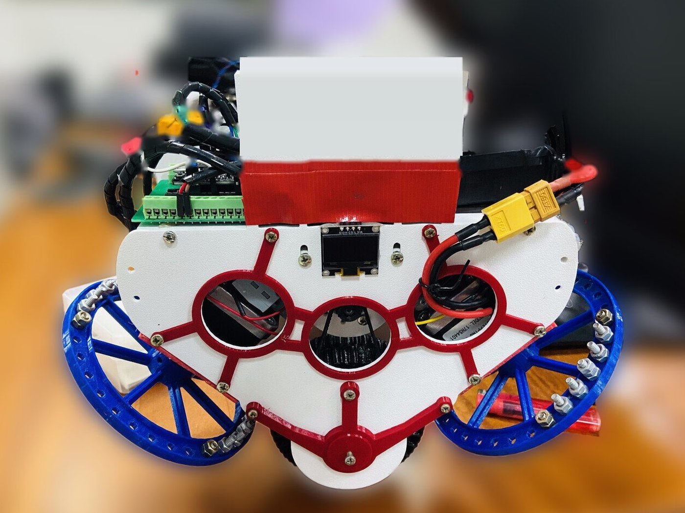
My robot: two reaction wheels on top, a ground wheel below.
01 Final-year project
Dual Reaction Wheel Unicycle Robot
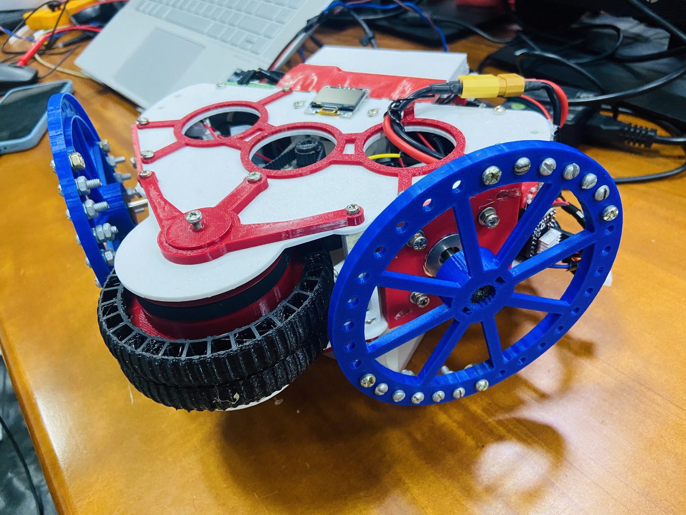
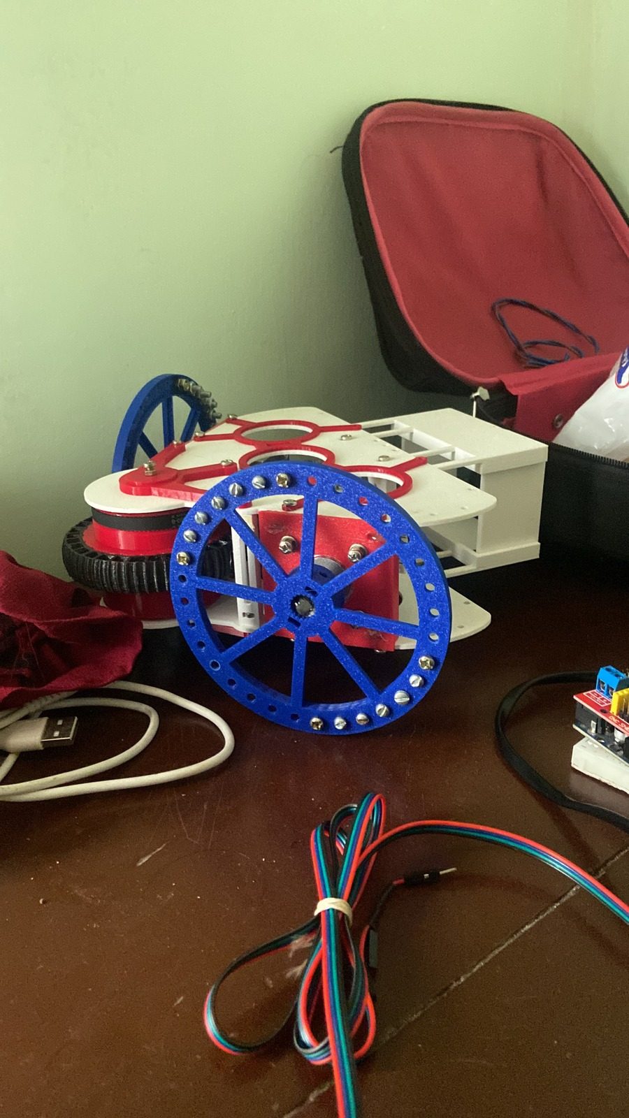
A self-balancing unicycle that uses two reaction wheels for balance and a ground wheel for recovery, aimed at carrying a payload of up to 500 g.
- ESP32 reads an MPU6050 IMU and runs the balance loop in real time.
- Two NEMA17 steppers on DRV8825 drivers act as reaction wheels with PD control.
- A Nidec 24H brushless ground wheel runs a PID recovery loop.
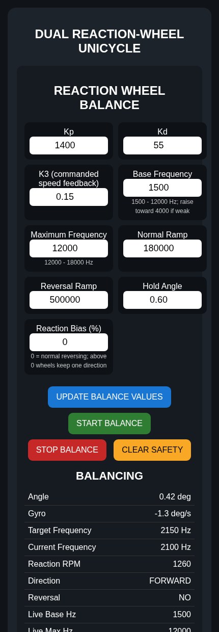
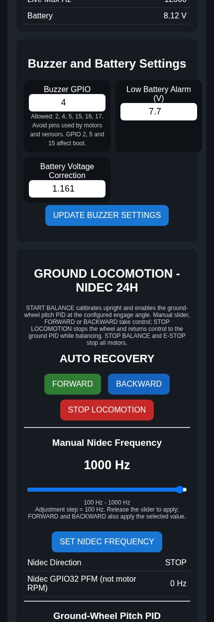
- A WiFi web page on the ESP32 tunes gains, speeds and limits from a phone.
- OLED display, battery voltage monitoring and a low-battery buzzer.
Two-wheel balancing robot
Arduino, MPU-6050, PID control and an L298N motor driver, tuned until it stayed upright on flat surfaces.
Servo motor tester
LabVIEW virtual instrument with several control modes, signal generation and live monitoring.
02 Code
ESP32 firmware (main version)
This is the main sketch that runs the robot. It reads the MPU6050, balances with the two reaction wheels, runs a PID recovery loop on the ground wheel and serves a WiFi page for tuning. The code has no comments on purpose. The explanation is below. The WiFi name and password in the code are placeholders.
What the code does
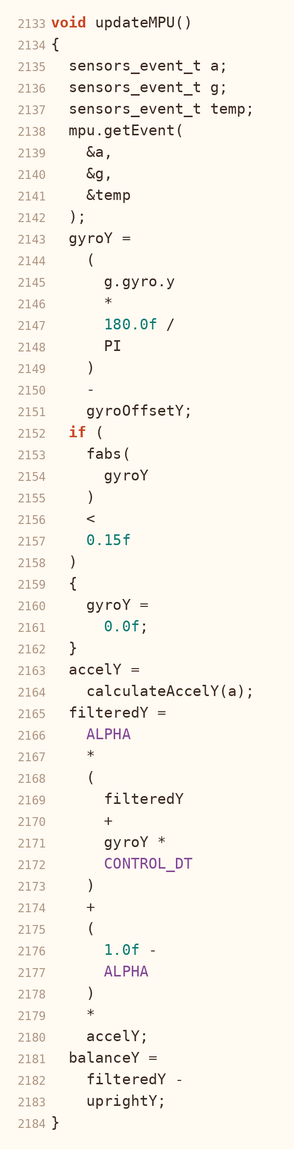
- Sensor reading. Every 4 ms (250 times a second) the ESP32 reads the MPU6050 over I2C. The gyro offset is measured at start-up while the robot is held still, and tiny gyro noise is zeroed.
- Filtering. A complementary filter mixes 98% gyro and 2% accelerometer into one steady tilt angle. The angle is measured from an upright reference that is calibrated at start, so upright is zero.
- Balance control. The reaction wheels use a PD controller: Kp 1400 on the tilt error and Kd 55 on the gyro rate. A small extra term (K3) lowers the demand when the wheel is already spinning fast. Past 20 degrees of tilt the code counts it as a fall and stops.
- Reaction bias. A "Reaction Bias" setting adds a fixed push (a percent of the maximum speed) to the controller output. It is for fixing a robot whose balance point is slightly off.
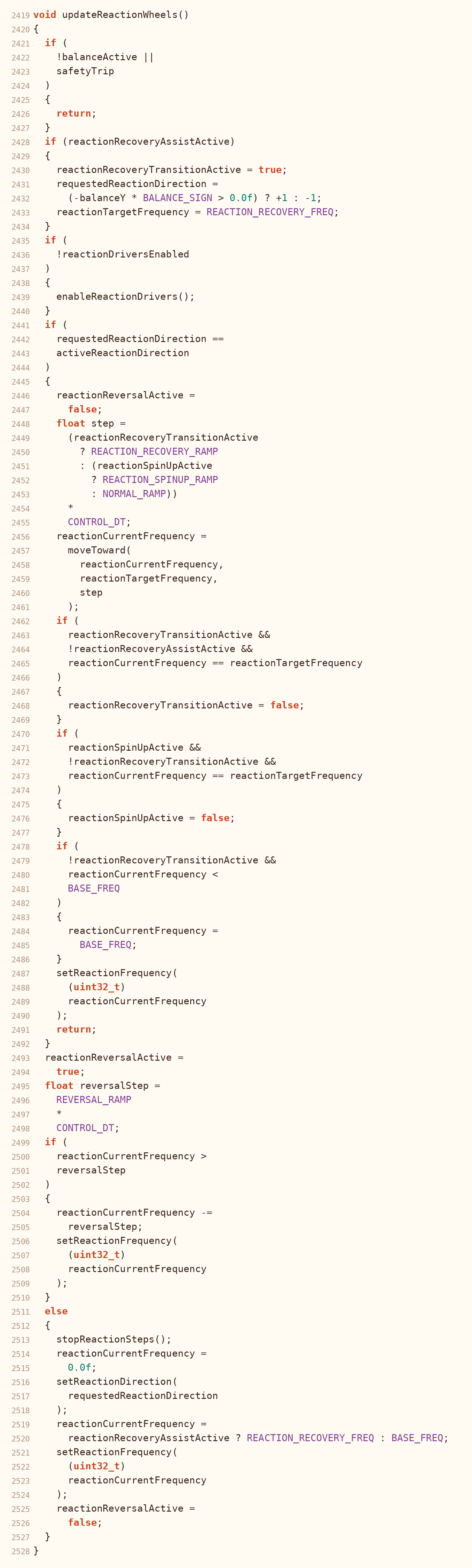
- Reaction wheels. The two NEMA17 steppers (DRV8825 drivers) get step pulses from the ESP32 timer. The controller output sets the pulse frequency (1.5 kHz to 12 kHz by default) and the direction. The speed changes on a fast ramp so the wheels react quickly, reversing uses an even faster ramp, and a slower spin-up ramp is used when balancing starts, until the wheels reach their target speed. Past 15 degrees the wheels get an extra recovery push.
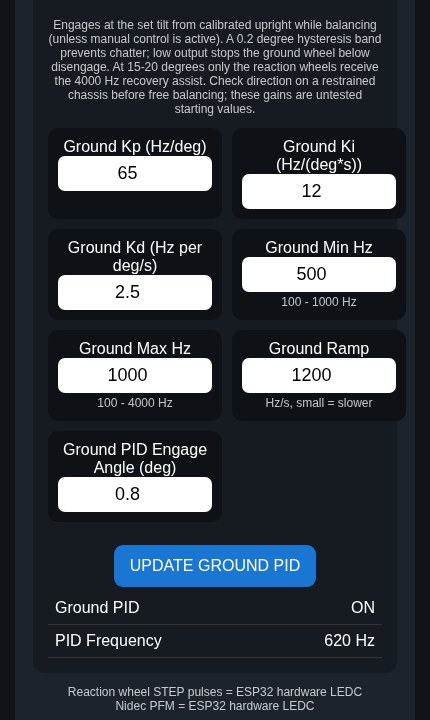
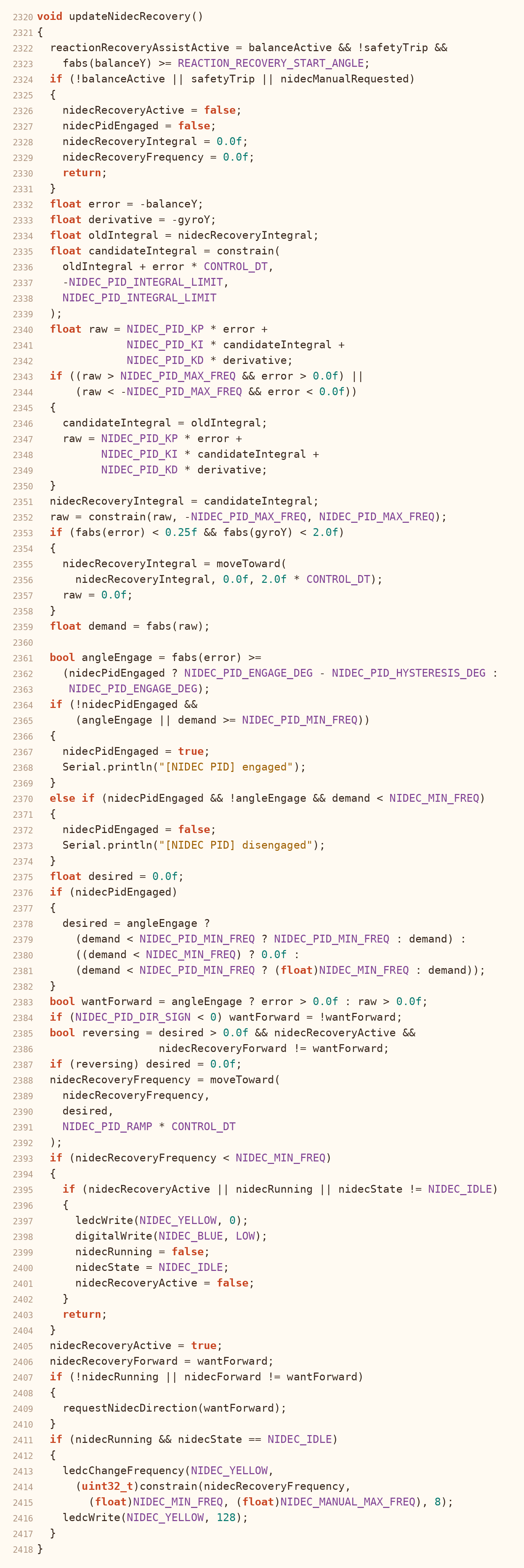
- Ground wheel. The Nidec 24H wheel has a PID loop (Kp 65, Ki 12, Kd 2.5) that starts at 0.8 degrees of tilt and drives the wheel to bring the robot back upright. It limits the integral and ramps the speed. A manual forward and backward control on the web page can take over from it.
- WiFi tuning page. The ESP32 makes its own WiFi network and serves a page you open on a phone. From it you can start and stop balancing, change the gains, frequencies, ramps, bias, engage angle and buzzer settings, and see live status. The values are saved in the ESP32 memory, so they stay after a restart or a new upload.
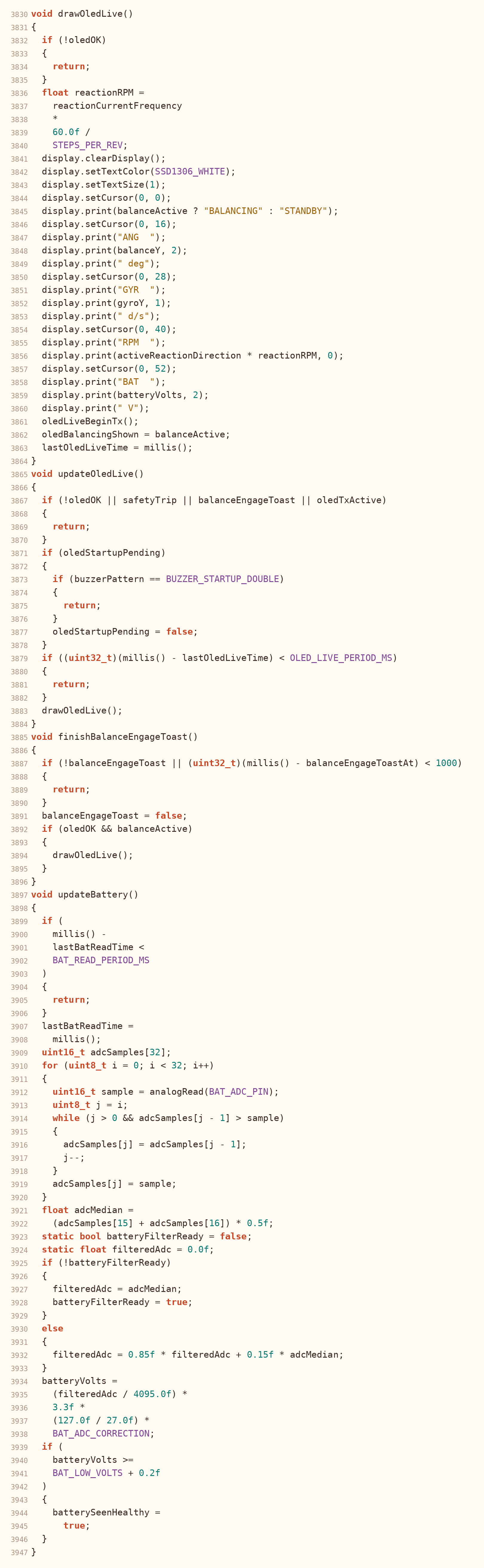
- Display and battery. The OLED shows a start-up splash, then the state (STANDBY or BALANCING), angle, gyro rate, wheel RPM and battery voltage, plus a thumbs-up when balancing starts. To keep the control loop fast, the screen is sent to the display in small chunks between control steps. The battery voltage comes from a voltage divider on pin 34. The code takes the median of 32 readings and smooths it.
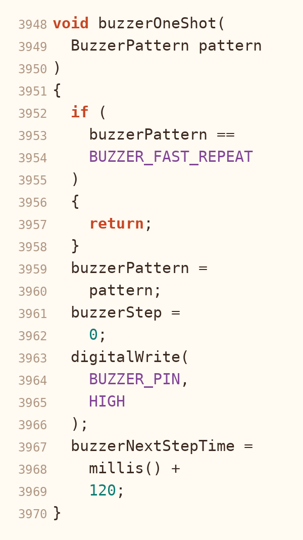
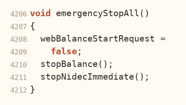
- Buzzer and safety. A buzzer gives a start-up beep, a fast repeating alarm on a fall or emergency stop, and a warning when the battery is low (7.7 V or below). An emergency stop button on a GPIO pin stops everything.
How the tuning page looks
The code, part by part
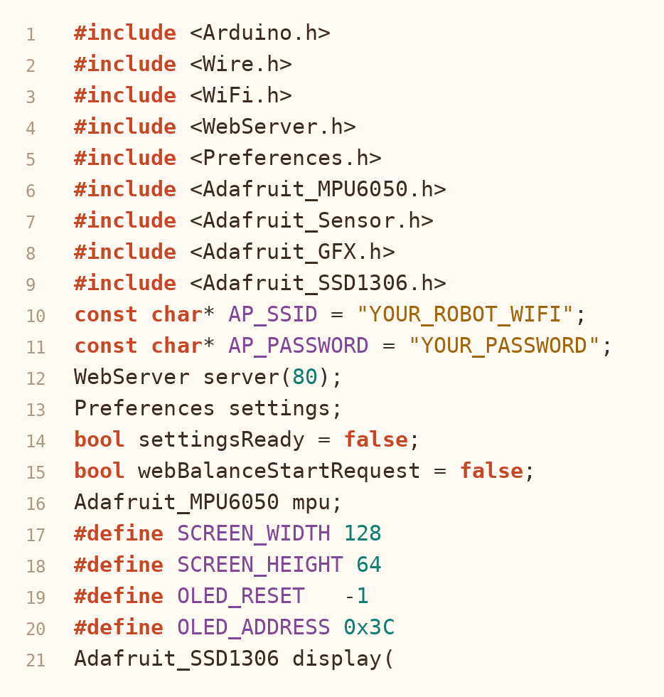
1. Libraries and settings
2. Reading the sensor and filtering
3. Balance control

4. Reaction wheels
5. Ground wheel PID
6. WiFi tuning page

7. OLED display and battery
8. Buzzer
9. Emergency stop
03 Industrial training
Industrial trainee, MediQuipment Limited
- Helped install medical equipment at client sites.
- Inspection and preventive maintenance of medical devices.
- Calibration support and performance checks.
- Fault finding and repair alongside engineers.
04 Skills
Education
BSc (Hons) Science and Technology, Mechatronics
Uva Wellassa University of Sri Lanka, 2022 to present
Let's talk
Open to junior roles in embedded systems, IoT and mechatronics.
thavarasathilothman@gmail.com